
- Discussion:
- see considerations for sliding screw placement
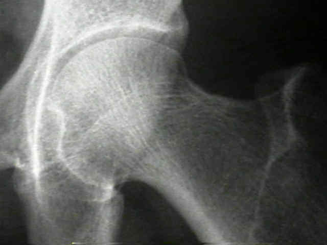
- osseous anatomy of proximal femur dictates where internal fixation device should be placed for maximum purchase in femoral head;
- maximum bone density is found in the area where compression & tension trabeculae coalesce in center of head;
- cancellous bone in the inferior portion of the femoral head has the weakest pull out strength, and therefore is least optimal area for fixation;
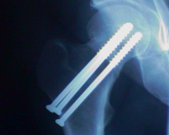
- stability at site of fracture is maximized by placement of 3 screws in an inverted triangular configuration w/ consider 1 inferior screw w/ 2 more superior screws;
- when four screws are inserted, use a diamond shaped configuration;
- Number of Pins:
- mechanical studies have not proved effectiveness of use of more than 3 pins, for Garden II frx;
- for Garden III and Garden IV frx consider insertion a fourth screw;
- Inferior Screw:
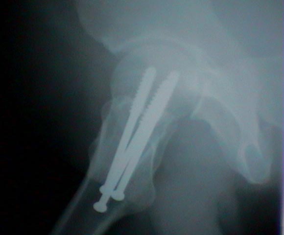
- generally inserted first, and is placed midway between anterior and posterior cortices (as seen on lateral view);
- guide-pin should lie inferiorly in the femoral head on AP view and in the center of the head on the lateral radiograph;
- guide pin should be placed as inferiorly as possible along the calcar;
- inferior screw must exit lateral femoral cortex above lesser trochanter, in order to lessen the chance of iatrogenic frx;
- when the patient is upright, the inferior screw resists compression;
- Two Superior Screws:
- after the inferior guide-pin has been placed, two more guide-pins are inserted w/ use of image intensification;
- when the patient is upright, the superior screws resists tension;
- when sitting the more anterior screw resists tension, whereas the more posterior screw resists compression;
- posterior screw is inserted as far peripherally as possible in the lateral plane and centrally in the AP plane;
- the remaining screw is inserted anteriorly (in the lateral plane) and centrally in the AP plane
Femoral neck fracture fixation: A biomechanical study of two cannulated screw placement techniques.
Subchondral screw fixation for femoral neck fractures
Crossed pins vs parallel pins in the treatment of femoral neck fractures.
Screw positions in femoral neck fractures. Comparison of two different screw positions in cadavers.
Intracapsular fractures of the neck of femur. Parallel or crossed garden screws?
Displaced Femoral Neck Fractures in Young Adults Treated With Closed Reduction and Internal Fixation