
- See: Notes for Wrightlock Spinal Fixation System: First, place the OCSTM Hook Holders on the caudal and cephalad hooks on the concave side. Next, tighten the nut on top of the hook holders using the OCSTM Hex Wrench (Figure 8). In preparation for using the OCSTM instrumentation, lubricate the Distraction with instrument milk. Position the Hinged Connectors over the Hook Holders (Figure 9). Next, position the OCSTM Distraction An-as already mounted on the OCSTM Distraction Rack into the Hinged Connectors (Figure 10). Finally, insert the OCSTM T-Handle into the cephalad Distraction Arm and apply distractive force (Figure 11). This will bring the spine to a nearly maximum corrected position. Maintain position and partially lock the locking sleeves into the hooks using the Sleeve Assembly Instrument (Figure 12).
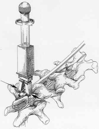
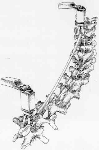

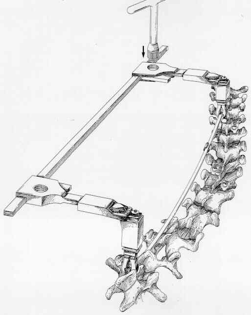
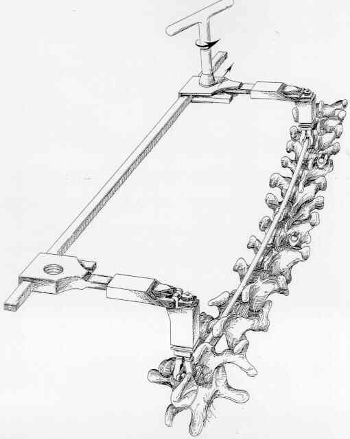 Figure 8 Figure 9 Figure 10 Figure 11 Figure 12 If the rod is too long, trim it to the proper length. Note the distance between the rod and the apical hook. If it exceeds the recommendations previously mentioned, adjust the shape with the in Vivo Rod Benders. Position the concave rod into the apical hook and use the Sleeve Assembly Instrument or the Sleeve Pusher to advance the locking sleeve into a partially locked position. If the rod cannot be easily positioned into the apical hook, delay this step until after the convex rod has been inserted. Covex Rod Insertion: Fully locked the lumbar hook onto the convex rod so the rod end protrudes minimally from the hook. Contour the rod for desired kyphosis, then cut the rod to length. Position the locking sleeves approximately on the rod. Use the rod to insert the lumbar hook at the selected caudal lumbar vertebrae on the convex side. The rod should pass through the body of the subapical hook. (Figure 13). Engage the locking sleeve for the subapical hook using the Sleeve Assembly Instrument. Keeping the Sleeve Assembly Instrument in this position, attach a Rod Clamp I cm below the hook/sleeve. Place the tip of the Curved Distractor between the Sleeve Locking Instrument and the Rod Clamp and apply light distraction load (Figures 14A and 14B). After appropriate hook position has been established, use the Sleeve Locking Instrument to fully lock the sleeve.
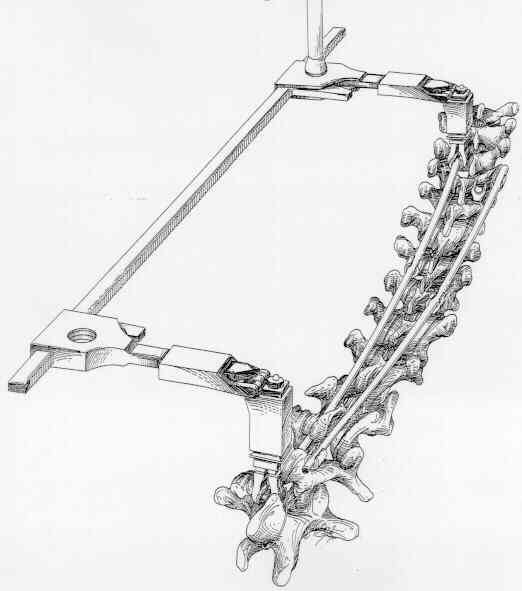
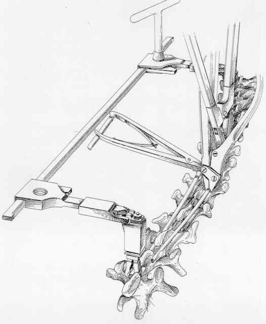
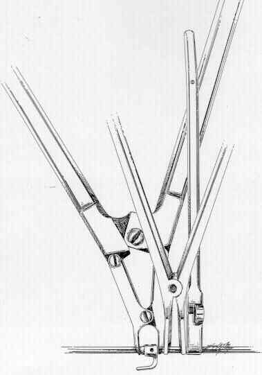 Figure 13 Figure 14a Figure 14b Position the top portion of the convex rod into the top hook. Use the Sleeve Assembly Instrument to advance the locking sleeve to a partially locked position. Check the seating of the hook and adjust if necessary. Use the Sleeve Locking Instrument to fully lock the top sleeve. If the concave rod has not been positioned in the concave apical hook, do so now. Bring the concave rod over the hook with the Rod to Rod Approximator. Depress the concave rod into its apical hook with the Rod Pusher and partially seat with the Sleeve Pusher or Sleeve Assembly Instrument. If this step cannot be accomplished easily, the Sagittal Approximator may be more effective. Once the concave rod is in the apical hook and the locking sleeve is partially seated, fully lock this hook. Couplers and Final Locking: If there is not much strain in the system, fully lock the upper concave hook before applying couplers. If there is substantial strain on the upper portion of the concave rod or the extent of the exposure prevents access of the Sleeve Locking Instrument around the outrigger, apply a coupler at the caudal and cephalad sites and lock in place. (Figures 15 and 16) When all the other components of the system are fully locked, most the distractive load on the upper concave hook will be transferred to other sites. Remove the outrigger unit and fully lock the upper hook with the Sleeve Locking Instrument. Fasten the cerclage wire around the spinous process of the lowest instrumented lumbar vertebra and the respective lumbar portion of the concave rod assembly. Secure the wire by twisting. (Figure 17).
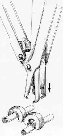
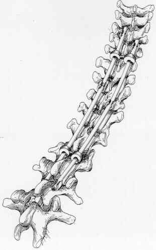 Figure 15 Figure 16 Figure 17